IT load
1 251kW
Reviewing possibilities for better data centers.
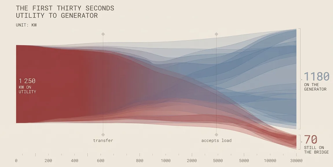
In the first second of a cut over the load leaves utility, crosses the bridge, and arrives on the generator with a little still in hand. Widths are indicative.
Every part a simulation can read. A part with no curve is a name, not a component, and the bank says which is which.
From the bank. Every count below is read when the page is drawn, from the parts file, the field list per class and the values actually recorded per part. Nothing is typed beside a class. A class whose symbol has not been drawn yet takes a dashed outline: that is a frame, not a drawing, and a class with nothing recorded says so in words.
The canonical record, what is unresolved in it, and where its figures came from.
Not a log. Three or four a year reach this page.